- 您现在的位置:买卖IC网 > Sheet目录233 > LT1701-7 (Power-One)AC-DC BATTERY CHARGER 54.5V 10A
T Series Data Sheet
?
500 Watt AC-DC Converters
Input Fuse
An input fuse (5 × 20 mm) in series with the input line (L)
inside the converter protects against severe defects; see also
Safety and Installation Instructions. For applications with
accessible fuse, see Option F .
Table 3: Fuse Type
mA/W
3.5
3.0
2.5
04026a
Series
LT
UT
Schurter type
SPF 6.3 A, 250 V
SPT 10 A, 250 V
Part number
0001.1012
0001.2514
2.0
1.5
1.0
Limit class D according
to IEC/EN 61000-3-2
Inrush Current
0.5
The converters exhibit an input capacitance of only 4 μF,
resulting in a low and short peak current, when the converter
0
3
5
7
9
11
13
15
17
Harm.
is connected to the mains. During switch-on, the converter
current can rise up to the input current limit I i L .
As a direct result of the low and short inrush current and
controlled charging procedure of the output capacitors, the
converter can be hot swapped. The LT inrush current is a
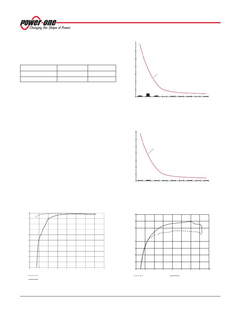
Fig. 3
Harmonic distortion at input LT1740-7Z, V i = V inom , I o = I o nom
factor 10 smaller than defined in the ETS 300132-1 standard
for Telecom systems. However the converter should be
plugged-in smoothly, giving time to the output capacitors to be
charged.
Input Under- /Overvoltage Lockout
If the specified input voltage range V i is exceeded, the
converter stops operation temporarily resulting in reduced
output power and increased RFI. The input is protected by
varistors. Continuous overvoltage will destroy the converter.
If the sinusoidal input voltage stays below the input under-
mA/W
3.5
3.0
2.5
2.0
1.5
1.0
0.5
Limit class D according
to IEC/EN 61000-3-2
04025a
voltage lockout threshold V i , the converter will be inhibited.
Power Factor, Harmonics
0
3
5
7
9
11
13
15
17
Harm.
Power factor correction PFC is achieved by controlling the
input current waveform synchronously with the input voltage.
PF
Fig. 4
Harmonic distortion at input UT1740-7Z, V i = V inom , I o = I o nom
1.00
0.98
04023a
0.96
0.94
04024a
0.96
0.94
0.92
0.90
0.88
0.86
0.84
0.82
0.92
0.90
0.88
0.86
0.84
0.82
0
2 4 6 8 10
12
14
16
I o [A]
0
2 4 6
8
10 12 14
16
I o [A]
UT1740-7Z at V i = 110 VAC
LT1740-7Z at V i = 230 VAC
Fig. 2
Power factor
BCD20023 Rev AB, 02-Nov-2010
V i = 110 VAC
Fig. 5
Efficiency versus load of LT1701
Page 5 of 31
U i = 230 VAC
www.power-one.com
发布紧急采购,3分钟左右您将得到回复。
相关PDF资料
LT5400AIMS8E-3#PBF
RES ARRAY MULT OHM 4 RES 8-MSOP
LTA201-TR-B/125N
SWITCH ROCKER SPST 15A 125V
LTA211-TR-W/125N
SWITCH ROCKER SPST 15A 125V
LUS001ST
SWITCH PUSH SPST-NO 0.25A 28V
LW3021A
SWITCH ROCKER DPST 20A 110V
LW3123-N4EE-H
SWITCH ROCKER DPDT 10A 125V
LXES1TBAA2-013
CERAMIC ESD DEV .55PF 6V SMD
LXES1TBAA4-005
CERAMIC ESD DEV 1.3PF 6V SMD
相关代理商/技术参数
LT1702-7
功能描述:AC-DC BATTERY CHARGER 48V 11A RoHS:否 类别:电源 - 外部/内部(非板载) >> AC DC 转换器 系列:* 产品培训模块:MP Modular-Configurable AC-DC Power Supply 特色产品:Configurable Power Supplies 标准包装:1 系列:MP
LT170A
制造商:未知厂家 制造商全称:未知厂家 功能描述:Linear Hall-Effect Sensor
LT170E2
制造商:未知厂家 制造商全称:未知厂家 功能描述:LT170E2 |Data Sheet
LT170Z
制造商:SEOUL 制造商全称:Seoul Semiconductor 功能描述:GREEN OVAL LAMP LED
LT171
制造商:SEOUL 制造商全称:Seoul Semiconductor 功能描述:RED LAMP LED
LT1711
制造商:未知厂家 制造商全称:未知厂家 功能描述:UNDERSTANDING THE SUBJECT IS CUSTOMER SERVICE
LT1711CMS8
功能描述:IC COMP R-RINOUT SINGLE 8-MSOP RoHS:否 类别:集成电路 (IC) >> 线性 - 比较器 系列:UltraFast™ 产品培训模块:Lead (SnPb) Finish for COTS
Obsolescence Mitigation Program 标准包装:2,500 系列:- 类型:通用 元件数:1 输出类型:CMOS,推挽式,满摆幅,TTL 电压 - 电源,单路/双路(±):2.5 V ~ 5.5 V,±1.25 V ~ 2.75 V 电压 - 输入偏移(最小值):5mV @ 5.5V 电流 - 输入偏压(最小值):1pA @ 5.5V 电流 - 输出(标准):- 电流 - 静态(最大值):24µA CMRR, PSRR(标准):80dB CMRR,80dB PSRR 传输延迟(最大):450ns 磁滞:±3mV 工作温度:-40°C ~ 85°C 封装/外壳:6-WFBGA,CSPBGA 安装类型:表面贴装 包装:管件 其它名称:Q3554586
LT1711CMS8#PBF
功能描述:IC COMP R-RINOUT SINGLE 8-MSOP RoHS:是 类别:集成电路 (IC) >> 线性 - 比较器 系列:UltraFast™ 标准包装:1 系列:- 类型:通用 元件数:1 输出类型:CMOS,开路集电极,TTL 电压 - 电源,单路/双路(±):2.7 V ~ 5.5 V 电压 - 输入偏移(最小值):7mV @ 5V 电流 - 输入偏压(最小值):0.25µA @ 5V 电流 - 输出(标准):84mA @ 5V 电流 - 静态(最大值):120µA CMRR, PSRR(标准):- 传输延迟(最大):600ns 磁滞:- 工作温度:-40°C ~ 85°C 封装/外壳:SC-74A,SOT-753 安装类型:表面贴装 包装:剪切带 (CT) 产品目录页面:1268 (CN2011-ZH PDF) 其它名称:*LMV331M5*LMV331M5/NOPBLMV331M5CT
